🚀 Flash Your BIOS Like a Pro!
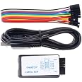
The KeeYees SOP8 Test Clip and CH341A USB Programmer is designed for efficient in-circuit programming of various 24/25 series BIOS chips. It eliminates the need for chip disassembly, making BIOS flashing simpler and more effective. The product includes a versatile clip that accommodates both wide and narrow body SOP8 chips, along with comprehensive PDF tutorials and software for seamless operation.


| Compatible Devices | Desktop |
| Graphics Card Interface | PCI Express |
| Video Output Interface | USB |
| Graphics Coprocessor | AMD |
C**Y
I love this tool
Love this little tool. Wish I had more excuses to use it. A friend locked themselves out of their laptop by setting a BIOS password that they couldn't remember. I cleared the CMOS memory several times, but the password persisted.I did some research and learned that modern laptops don't store BIOS passwords in CMOS. Instead, they are stored in non-volatile memory, such as the eeprom on the BIOS chip itself. Further research indicated that this particular laptop likely used an AMI BIOS implementation, and that the password could likely be decrypted or cleared.I happened to have this tool on hand and was itching for a reason to use it. I had never used a BIOS programmer before, so I read a few guides, identified the BIOS chip, and downloaded and reviewed its datasheet. I booted Ubuntu on another laptop and installed flashrom. I verified that flashrom was compatible with the BIOS chip. I hooked up the clip, and flashrom recognized the chip on the first attempt.I dumped the ROM three times and confirmed the checksums for each dump matched. I used UEFITool and confirmed that I was looking at an AMI BIOS and that the AMITSESetup variable was present. I found a tool on GitHub named AMITSESetup Decryptor & Unlocker that was unable to decrypt the password, but it did clear the password from the ROM dump. I flashed the modified ROM back to the BIOS chip, and much to my surprise I was able to boot the computer with no issues and no BIOS password prompt!
E**!
Excellent
Excellent product
J**Y
Packaging
Would give a 5 but packaging wasn’t great one of chips were broke, another had bent prongs, unsure if can be bent back without breaking, other than that though delivery was fast and did include all items and seems to be working perfectly so far!
C**R
No modifications needed
A bunch of people said this requires some modification to make it compatible with 3.3V chips due to a "design flaw" (which i regrettably did because it was easy enough) but they're wrong. What happened is that some idiot with a multimeter saw 5.0V going to the pins and had themselves a freakout without checking amp draw (which is less than a milliamp). And then a bunch of other people including pseudo electronics geniuses started blindly repeating this falsehood, wasting everyone's time.What's important is that the voltage drops to 3.3V without any modification whatsoever when you're actually performing read/write operations on a 3.3V chip. For the reviewers saying not performing the modification fried their 3.3V chip with such a small amp draw, my best guess is that they had the bios in the wrong slot, the pins lined in the wrong order, or the clamp was simply not making good contact as they're notorious for, and after reading a bunch of "must modify or else" comments they probably assumed their chip must have "fried".Electronicsrepairschool on youtube explains the issue quite well. Although his videos are a little long winded for my taste at least he knows what he's talking about.I flashed 2 winbond motherboard bioses, one with the mod and one without and both processes worked just fine. I did not use the clamp because all indications are that it's a bit flakey and the 2 chips i flashed were the removable kind.
G**S
Helped me bring my Gaming PC back to Life
It took a lot of Youtubing and guess work to use. However, this small price to pay here did everything I needed it to in order to get my expensive gaming laptop back together and reset the bios.I will say that I have a moderate knowledge around computers, and I am very willing to trial and error my way through a project. That being said, sending in my PC would of been $1000 out of warranty to get it fix. I did it myself and spent 2 weeks troubleshooting which got me to hear and only having to pay for this to fix my issue after ripping my laptop open myself.I would recommend going online to find the most up to date software to use for this.
E**S
Failed after a single use, would not detect
While the incuded clip and accessories were helpful and decently built, the CH341A device itself failed after only a single use.TL;DR - The USB Type A plug was defective. This part is the rectangluar thing that plugs into the computer. It failed to maintain a reliable D+/D- connection due to issues with manufacturing and/or a severe (but difficult to detect) quality problem with the part itself.TL;DR2 - If your device arrives with a 'slanted' USB-A plug (slanting downward from the board plane about 10-15 degrees) its likely that it will suffer from similar issues. If you see issues initiate a return immediately instead of being curious and stubborn like me. :)Read on for some data from testing and analysis on the USB-A plug part itself.There are a few different revisions of this "black CH341A" device circulating via different sources. There are a lot of resoruces for details on these and schematics so I won't get into that here.A quick visual inspection revealed a few interesting facts.- The board's connections were generally very well soldered, which is good.- The board's parts were generally very well placed, fully within the pads - with one exception.- The CH341A chip itself was placed with an offset of 1/8 of a pin's width to the right of its intended pads. This isn't a serious issue - connectivity wasn't impacted and no bridging was present - but it may indicate poor QA on the line, at least for this run of parts.- The USB-A port frame is solidly mounted to the board with the through-hole ground lugs on either side soldered quite well to the board, which is good.- The four primary USB connections (GND, D+, D-, Vcc/5V) were also soldered in pretty well, which is also good.- The USB-A plug itself was tilted down slightly from the board's plane, by about 10-15 degrees, which is a concerning indicator that manufacturing QA might be very, very lax, but this isn't an immediate dealbreaker.So visually things looked pretty good, with a few minor exceptions that I'd generally consider within acceptable range for a cheap device like this. I've definitely seen a lot worse in a visual inspection of an inexpensive electronics hobby part and most of those parts end up working fine. So far, so good.The failure pattern looked like this:1. Attached to a bare (not in-circuit) W25Q64FV SPI EEPROM via clip (clip worked fine)2. Plugged in to USB 2.0 port on Ubuntu 20.04 Linux system (detected, USB device mounted successfuly)3. Used flashrom 1.12 to read the ROM 3 times, write once, read 3 times to verify (worked great)4. Unplugged from USB port (device removed successfully)5. Attached to new, bare (not in-circuit) WV25Q64 SPI EEPROM via clip (clip worked fine)6. Plugged into same USB 2.0 port (*power light turned on, did not detect at all*)7. Unplugged and re-plugged several times (*power light turned on, intermittently detected but failed to enumerate*)After repeating step 7 a few dozen times, here are the results from my notes. I used `dmesg -w` to follow kernel logging to see detection/enumeration events.1. No detection2. No detection3. Detected device attach, failed to enumerate device4. No detection5. Detected device attach, failed to enumerate device6. No detection7. No detection8. No detection9. No detection10. Detected device attach, enumerated successfully11. No detection12. No detection13. Detected, failed to enumerate14. No detection(same until try 30)After this extended test, I tried various depths of insertion of the USB device. I've encountered similar problems with other USB Type A devices and cables that ended up being related to poor connection within the USB Type A connector itself. In those cases, "wiggling" the plug often helped estabish a proper connection, at least temporarily.To test this I tried removing the plug and inserting it to different depths while holding it long enough to allow it to enumerate (about ~1.5-2 seconds).Test 1, 3mm depth: Powers on, no detectionTest 2, 4mm depth: Powers on, no detectionTest 3, 5mm depth: Powers on, detects device, no enumerationTest 4, 6mm depth: Powers on, detects device, enumerates successfullyTest 5, 7mm depth: Powers on, detects device, no enumerationTest 6, 8mm depth: Powers on, detects device, no enumerationTest 7, fully inserted flush with port: Powers on, no detectionWhile the device was attached and failing to detect, I probed the key voltages with a multimeter. All of the power delivery was fine. The CH341 was powered with 5V on its Vcc pin, the ADS1117 was powered with 5V and outputting 3.3V succcessfully, and the 5V and 3.3V pins on the headers were succesfully powered as well.Given that data, it looked like the D+ and/or D- connections were failing to establish connection properly within the USB Type A plug.I'm a curious person and, rather than waiting for a return cycle, I wanted to get this working ASAP to clear a few projects off my bench.*Don't try this at home, since you probably can't reutrn it after doing any desoldering! Providing this part to share my analysis and experince*I desoldered the USB Type A plug and found that the D+/D- lines were definitely suspect. The part they chose to use on this run was more flimsy than I'm used to seeing. While desoldering, the pins themselves easily separated themselves from the frame. This can happen when desoldering this type of part but I've never seen internal pins this loosely mounted within a Type-A plug frame. Again, not a serious problem - the heat required desoldering these types of higher-thermal-mass plugs generally destroys the plug in the process. But this one fell apart way easier, and way faster, than expected.After cleaning up the remaining solder and attaching a new, more robust Type A plug part the device powered on when connected but failed to enumerate. I'm guessing that the heat from desoldering the port (~300c) likely propigated to other parts via the large ground planes, so this is kind of expected.So that's it. Basically, a shoddy USB-A connector made this device pretty useless unless it was connected and held in place at just the right depth. That won't work for most of us. So check your USB connector and if it fails to detect or enumerate, just ask for a replacement like I should've done. :)
TrustPilot
vor 1 Monat
vor 1 Monat